
Complex Biosystems Inc.

ViewPort suite
|
The ViewPort suite supports: (i) high performance scientific data visualization, as well as integrated development tools to design (ii) front end user interfaces, and (iii) batch processing system for high performance computing applications.
The viewer is built on OpenGL and OpenMotif, and takes advantage of specialized graphic processing units in the rendering and 3D affine transformations of graphic objects. It supports the display of most data formats encountered in Science and Engineering, ranging from curves, surface models, volume rendering modelsm with lighting and texture. It is a complete viewing system.
In order to accomodate the large number of graphic data formats encountered in Science and Enginnering ViewPort stores all the graphic objects it manipulates in a relational data base (center in the figure). Once inserted in the data base a graphic object is assigned a standrad parameterization. This way I/Os to disk and memory can be optimized for performance. This organization faciliates searches and various data mining operations. The ViewPort Data Base Manager has a command line interface to import/export images or other graphic objects to/from the data base. The back end of the Data Base is supported by Berkeley DB which is offered free of charges by Oracle. The DB manager has an open architecture. Meaning that the format of the graphic objects are documented and a developer can link his/her own code to his system. This way one can write custom modules to import/export any user-defined graphic objects.
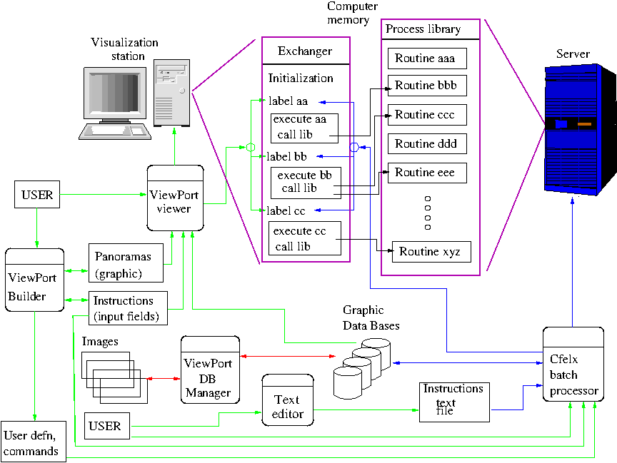
The ViewPort system is more than a scientific data viewer. When the viewer is supplemented with the Builder the system becomes an integrated development environment (IDE) for front end user interfaces. It is well particularly suited for scientific applications coping with complex data sets. As suggested in the Figure, the IDE can link a developer's application with the viewer. This way an operator can run processes in the linked applications and then display the results in several panoramas (graphic windows).
The builder includes a Graphic User Interface (GUI) to: design panoramas (graphic windows) in which graphic objects are displayed, specify how these objects are manipulated, and assign several attributes (e.g. lighting) to the scenes in which they are displayed. Input data and control buttons are displayed in a differeent type of window termed instruction windows. From the GUI, the developer positions all input fields, decides the method employed to acquire the data (text fields, sliders, or choice buttons, to name a few), associate these fields to variables in his/her code, and insert butons which function is tu jump execution to specific segments of a developer code that are identified with labels.
The suggested development practice is to write a special routine called an Exchanger that contains a label for each action button. The code following the label retrieves information displayed in instruction windows, perform some validation, process the data, and return the data into graphic objects sockets that are recognized by the viewer. As illustrated in the Figure the processing part may use routines from external libraries wrote with any procedural language. There are no restrictions, as long as the library is written with object code compatible with the microprocessor on which the system is running. A most important advantage is that since the developer hass full control over its application, there are no performance penalty to pay to operate his/her application with this front end user interface. Still (s)he is relieved from coding all aspect of user interaction.
The component Cflex which stands for Control of Flow of Execution is the batch counterpart of the builder. Similarly to the interactive IDE, the batch processor Cflex is linked with the developer's code. The code should be organized as illustrated in the Figure, i.e., the application is subdivided into a set of operations. An exchanger acts as a hub, including an entry labeled with a tag for each opeartion. Processing within each operation can be extensive since calls could be made to specialized external libraries. If a developer elects to, the outputs can be wrote in the the graphic DB. This way visualization could readily be performed upon completion of the batch jobs. The main advantage is flexbible system for high performance large scale applications where input parameters and graphic outputs can be easily managed and readily visualized. The last item being important for discovery since elaborate reflections takes place in short term memory, that is facilitated with interactive visualzation.
Not shown in the Figure is an instrumentation module. Still under development it is expected to be released in Fall 2015. This component provides functionality to stream data from/to acquisition/control boards to the ViewPort viewer. From its application a developer loads communication modules in control or acquisition boards. (S)he also defines communication sockets to directly exhchange data between the viewer and the electronic boards. This way there are no performance penalty to pay to control an instrumentation with ViewPort, and real time applications can be readily developed.